 Shrimpware
Project: Five Button Joystick
Difficulty: Medium
for Arduino
Order your own BreadBox kit
Overview
A five position switch is like a joystick. You can push it to all four sides and you can push down in the center. Each of these motions triggers a switch that can be read by the Arduino. In this project we will wire up the five position switch to the Arduino and use it to control the BreadBox servos.
Parts
In addition to the BreadBox kit you will need:
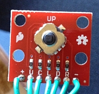
- A five position switch. I used part BOB-11187 from Sparkfun.
- A five connector header. I used Adam Tech RS1-06-G-.561-A11596 from Jameco.com.
- 24 gauge wire (stranded is best)
- A two connector cable (you can use a three connection servo extension cable)
Tools
Soldering iron, nippers, needle nose pliers
Step by Step
- Cut Wire - Cut 7 sections of the 24 gauge wire, each 12 inches long. Remove 1/4 inch of the insulation from each end. Use the soldering iron to "tin" one end of each wire. Tinning means to heat the wire with the soldering iron and melt a little solder onto each one; not much, just a little bit. Tinning makes the next steps go easier.
-
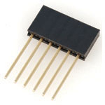 Prepare Header - We will only need five of the six positions on
the header. Use the soldering iron to tin five of the pins sticking
out of the header.
Prepare Header - We will only need five of the six positions on
the header. Use the soldering iron to tin five of the pins sticking
out of the header. -
 Attach 5 Wires To Header - Use the needle nose
pliers to make a small loop in the tinned end of 5 of the cut wires.
Take one of the wires and slip the loop over one of the tinned pins
on the header. Use the pliers to squeeze the loop tight. With the
soldering iron solder this wire to the pin. This is where that
pre-tinning makes the job much easier.
Attach 5 Wires To Header - Use the needle nose
pliers to make a small loop in the tinned end of 5 of the cut wires.
Take one of the wires and slip the loop over one of the tinned pins
on the header. Use the pliers to squeeze the loop tight. With the
soldering iron solder this wire to the pin. This is where that
pre-tinning makes the job much easier.
Not pretty, but it works.
Do the same with four of the other wires. -
 Attach 5 Wires To Joystick - Solder the five
wires to the MIDDLE five contacts on the switch. We want to have the
following contacts wired to the header: Up, Down, Left, Right,
Center.
Attach 5 Wires To Joystick - Solder the five
wires to the MIDDLE five contacts on the switch. We want to have the
following contacts wired to the header: Up, Down, Left, Right,
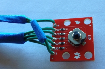
Center. - Two Wire Cable - Take the 12 inch two wire
cable and cut off one end. Solder the wires to the two remaining
joystick pins: VCC and Ground. These two pins are on the out side of
the other five pins.
The little blue tape is on the Ground wire. I put one on the other end of the same wire. Makes it easier to hook up correctly. -
 Connect the Cables - If you have an assembled
BreadBox, then remove the cables from the analog inputs. Place the
six connector header on the sensor shield so that it spans the S
input for five of the analog inputs.
Connect the Cables - If you have an assembled
BreadBox, then remove the cables from the analog inputs. Place the
six connector header on the sensor shield so that it spans the S
input for five of the analog inputs.
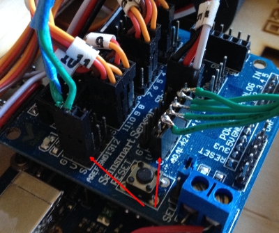
Attach the two wire cable to a convenient VCC / Ground pair.
Look for the little red arrows in the photo to see how I hooked them up.
You can see the six pin header spanning the analog inputs. And the one unused pin is hanging off the side. - Power Up - Now connect your typical two USB power
cables. One between your computer and the Arduino board and one to
the sensor shield. Since we're running servos we can't just use the Arduino
power. The servos draw too much current, which drops the VCC voltage
and causes the Arduino to reset
over and over. I think a second USB power supply is a must.
NOTE: Your sensor shield may have a jumper to indicate whether its power will come from the Arduino board or from an external power source. Be sure this jumper is set to use the external power source. If not, you could damage your Arduino or your computer's USB power. - Software - Cut and paste the software below into your Arduino IDE
- Run it - Compile the software and download it to your Arduino. (The "go" button in the IDE.) Once the software is downloaded you can open the Arduino serial monitor (CTL SHIFT M). You should see "Initialized" on the screen.
Adjustment
- High or Low - Look at the serial monitor while the program is running. Once a second the program prints out the values of what it thinks are up, down, left, etc. You should see them all as over 1000. If the values are all close to 0, then you have reversed the two wire cable for VCC / Ground.
- Button Order - Each switch on the joystick is connected to one of the analog inputs 0 - 4. It's possible that your wires are not connected in the same way mine are. To test this watch the serial monitor. Now press the joystick left and hold it. One of the numbers should go to 0. Change the constants at the top of the program so that the action corresponds to the correct joystick switch.
Operation
With the software below you can use the joystick to make the servos move slowly clockwise or counter clockwise (the left and right buttons); slowly spread open or close (the up and down buttons); return to the 90 degree position (center button).
Here's a short movie of the whole thing running.
Code
/*
* five position thumb control servo test jig
* Left / Right will move servos left and right
* Up / Down will move servos 3,5,6 one way and 9,10,11 the other
* Center press will move them all to 0
*
* (c) 2013 Jim Schrempp shrimpware.com
*/

#include <Servo.h>

#include <Serial.h>

// input pins for switches

const int c_up     = 0;
const int c_middle = 1;
const int c_left   = 2;
const int c_down   = 3;
const int c_right  = 4;

Servo servo3;
Servo servo5;
Servo servo6;
Servo servo9;
Servo servo10;
Servo servo11;

const int c_servoHomePosition = 90;
int servoLeftPosition = c_servoHomePosition;   // Initial position is the home position
int servoRightPosition = c_servoHomePosition;

void setup() {

  servo3.attach(3);
  servo5.attach(5);
  servo6.attach(6);
  servo9.attach(9);
  servo10.attach(10);
  servo11.attach(11);

  Serial.begin (9600);
  while (!Serial) {
    // wait for the Serial interface to become ready
  }

  Serial.println ("Initalized");

}

void LeftServosToPosition (int newPos) {
  servo3.write(newPos) ;
  servo5.write(newPos);
  servo6.write(newPos);
}

void RightServosToPosition (int newPos) {
  servo9.write(newPos);
  servo10.write(newPos);
  servo11.write(newPos);
}


void loop() {

  // Read each switch. If the switch is Low (which is ON) then adjust the
  // appropriate servo positions

  int readValueL = analogRead(c_left);
  if (readValueL < 500) {
    servoLeftPosition = servoLeftPosition - 1;
    servoRightPosition = servoRightPosition - 1;
  }

  int readValueR = analogRead (c_right);
  if (readValueR < 500) {
     servoLeftPosition = servoLeftPosition + 1;
     servoRightPosition = servoRightPosition + 1;
  }

  int readValueU = analogRead (c_up);
  if (readValueU < 500) {
     servoLeftPosition = servoLeftPosition + 1;
     servoRightPosition = servoRightPosition - 1;
  }

  int readValueD = analogRead (c_down);
  if (readValueD < 500) {
     servoLeftPosition = servoLeftPosition - 1;
     servoRightPosition = servoRightPosition + 1;
  }

  int readValueM = analogRead (c_middle);
    if (readValueM < 500) {
    servoLeftPosition = c_servoHomePosition;
    servoRightPosition = c_servoHomePosition;
  }

  // Make sure the servo positions haven't gone too far
  if (servoLeftPosition <   0) servoLeftPosition =   0;
  if (servoLeftPosition > 180) servoLeftPosition = 180;

  if (servoRightPosition <   0) servoRightPosition =   0;
  if (servoRightPosition > 180) servoRightPosition = 180;

  // Move the servos to position
  LeftServosToPosition ( servoLeftPosition );
  RightServosToPosition ( servoRightPosition );

  // This bit is to make sure that we only write to the
  // serial port once a second. Without this kind of check
  // the code would write to the serial port every time
  // the main loop is executed, and that will overrun
  // the output buffer very quickly.
  static long lastWriteTime = 0;
  long currentTime = millis();
  if (currentTime - lastWriteTime > 1000) {
     lastWriteTime = currentTime;
     Serial.println ("left, right, up, down, middle, left position, right position ");
     Serial.print(readValueL); Serial.print(", ");
     Serial.print(readValueR); Serial.print(", ");
     Serial.print(readValueU); Serial.print(", ");
     Serial.print(readValueD); Serial.print(", ");
     Serial.print(readValueM); Serial.print(", ");
     Serial.print(servoLeftPosition); Serial.print(", ");
     Serial.print(servoRightPosition);
     Serial.println ("");
  }

  delay(15);

}
(c) 2013Shrimpware LLC All Rights Reserved